Attitude and Altitude Control of a Drone
Robotics is an educational and technological branch that deals with systems composed of automatic mechanical parts in conjunction with integrated circuits, resulting in motorized mechanical systems controlled by electrical circuits and computational intelligence. Robotics is also the subject of study in several areas: computing, aerospace, mechanics, automation, electrical, etc. Society is increasingly using robots for its tasks. This technology, now adopted by many factories and industries, has generally been successful in areas such as cost reduction, increased productivity and reduction of problems in several aspects.
The drone is an unmanned aerial vehicle. It is controlled remotely and is supported by the thrust generated by the propellers. It consists of an aircraft that can be moved in all directions with precision, thus ensuring safe and efficient use, which contributes to various actions and activities in numerous sectors. Currently, the term Drone has been widely used for quadcopters, but is not limited to quadcopters. There are also hexacopters (6 propellers), octocopters (8 propellers) or even small airplanes with fixed or mobile wings. The quadcopter is an underactuated mechanical system with 6 degrees of freedom and four actuators, which is a system that has a number of control inputs smaller than the number of degrees of freedom.
The positive point is that there is a reduction in project costs and in the weight of the final system, as it avoids the use of additional actuators. Furthermore, in situations where there is a possibility of actuator failure, the system, initially designed to be fully actuated, can continue to operate in these critical situations, which avoids major problems. On the other hand, the quadcopter has a nonlinear model that makes it somewhat difficult to simplify and linearize dynamic control. Drones are suitable for various applications, and for each of them they need to have sufficient autonomy to be able to perform a specific intended task. The main tasks that a drone can perform are following trajectories, monitoring and scanning a certain area and transporting objects, tasks that can be worked on and applied to different areas and sectors.
Theorical Basis
Before implementing the specific objectives that consist of the integral development of a drone with robust digital PID controls to ensure stability in the prototype area, it is necessary to contemplate some basic fundamentals to ensure the understanding of other more complex components of the physical functioning of the prototype.
Degrees of freedom
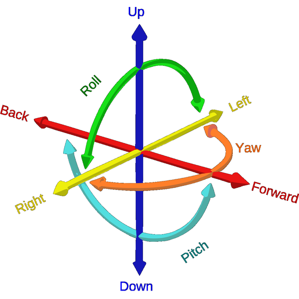
Degrees of freedom are, in Physics, a generic term used to refer to the minimum amount of real numbers needed to completely determine the physical state of a given system. The position of the drone's center of mass can be easily described by 3 coordinates in space, but to obtain control of the drone one must be aware of its orientation in space as well. To describe the dynamics, one must consider the position and one must describe the orientation in space as a function of time. It is necessary to determine the positions of all points of the drone in space, which can be obtained from the 6 coordinates (φ, θ, ψ, x, y, z) that represent the roll, pitch, yaw and the x, y and z coordinates of the center of mass, respectively.
Orientation
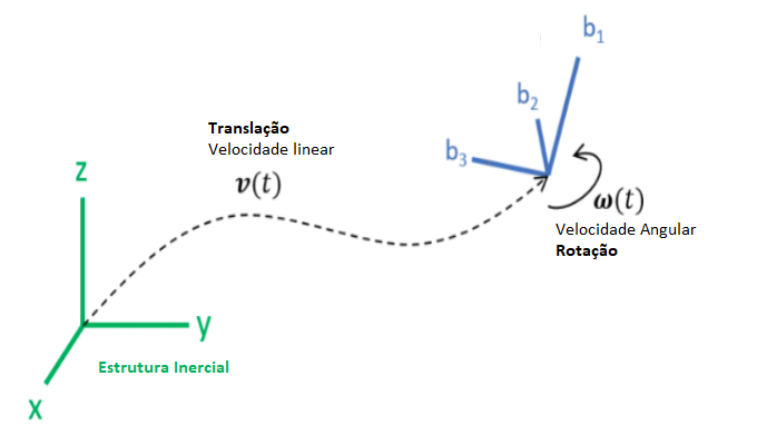
The position of the drone can be described by the coordinates x, y and z, establishing the respective distance from a fixed origin on Earth known as the inertial reference system, and the coordinates are generally in the cardinal directions North, East and Down. To represent the orientation or attitude of the vehicle, the angles φ, θ and ψ are used relative to the body frame reference, which is a coordinate system with its origin at its center of mass.
Euler angles
Using the Euler angles (θ,φ,ψ) one can find the final orientation of the drone with respect to the orthogonal system using an inertial transformation matrix. It is assumed that (x, y and z) is an inertial orthogonal reference system and (b1, b2 and b3) is the final reference system. Rotating around one of the axes results in the displacement of the other two axes with respect to the axes of the inertial orthogonal system. At the same time, the axis of rotation remains parallel to the corresponding inertial axis. The axes of the rotated body system can be represented as inertial trigonometric function equations. The trigonometric equations can be further expressed in matrix forms. Similarly, we can obtain two other matrices by rotating two other axes of the body. The Figure below shows the rotation of all the axes b1, b2 and b3 with respect to the orthogonal inertial axes, trigonometric function equations and their matrix representations.
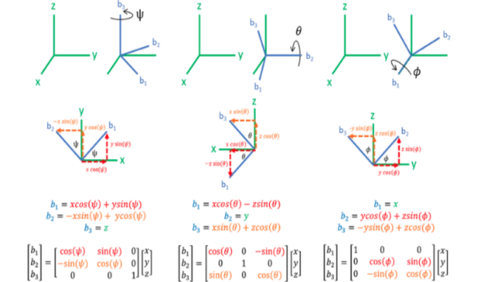
The Figure above shows the three rotation matrices referring to the yaw, roll and pitch angles. To obtain a single rotation matrix, simply multiply them as shown in Equation (1):
Since the above matrix is orthonormal, one can use the transpose of the matrix transformation to obtain:
From Equations (2) and (3), one can obtain the orientation in 3D space from an initial and final reference point of the drone.
Pulse Width Modulation
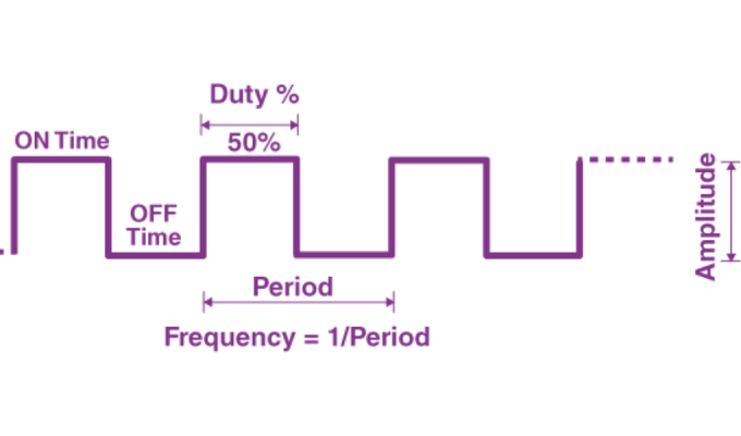
Pulse Width Modulation (PWM) is the acronym for Pulse Width Modulation. The PWM technique is widely used in electronics, especially in switching power supplies. In addition to this use, the PWM technique can also be used to control motor speed, brightness control, servo motor control, and other applications.
PWM works in a similar way to a switch in a circuit that, when turned on, allows all the energy to pass through, and this energy is applied to the load in its entirety. When the switch is turned off, no energy reaches the load. The time that the switch remains closed or open is then controlled to apply the average power to the circuit in which the pulse remained active. For PWM to work, considering the square wave, the pulse width of the wave must be varied, the so-called Duty Cycle. Mathematically, two parameters are used: the period and the pulse width, defined as a percentage. By varying the pulse width, it is possible to vary the amount of energy delivered to the load. Power and voltage values are made available to the load according to the needs of the circuit. An advantage of applying PWM is that the signal remains digital throughout the path from the processor to the controlled circuit, and no signal conversion is required.
PID Control
Dynamic control is very important for the proper functioning of the drone. Without a control system, the open loop dynamics of the drone are unstable. There are many control strategies and algorithms, but for this project, a powered control system consisting of a PID controller will be used. A PID (Proportional Integrative Derivative) controller has three control terms. The input to the PID controller is an error (difference between the current value and the desired value), which is multiplied by the PID gains to achieve control of the plant or process. The Proportional term compares the desired and current values and simply multiplies the error value by a constant. The Integrative term removes the steady state error by integrating the error value over time until it reaches zero. The Derivative term estimates the future error and removes it. It estimates the control action by the rate of change of the error with time and multiplies it by the derivative constant.
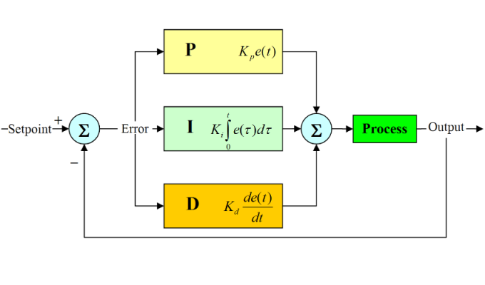
The output signal u of the PID controller as a function of time is given by:
The Model
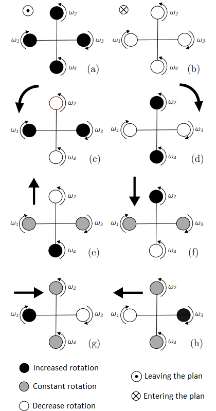
The drone is composed of four equidistant brushless motors. The motors on one arm rotate clockwise, and the motors on the other arm rotate counterclockwise. In this way, the effect of the resulting torques will be nullified, preserving the angular momentum of the structure. The movement of the drone is obtained by the variation of the four angular velocities (1, 2, 3, 4) of the respective motors. The yaw movement, for example, occurs when the resulting angular momentum of the four motors is non-zero, causing the quadriceps to rotate around the z axis.
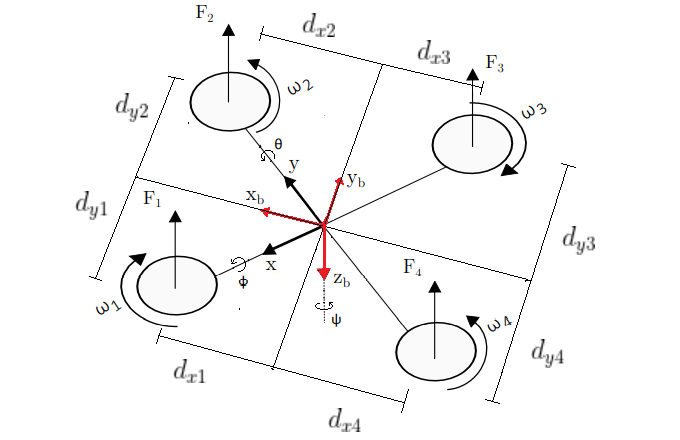
According to the image above, it can be inferred that the resulting force acting on the drone generated by the propulsion of the engines is given by:
The Moment about the x-axis () of the opteran hip is obtained by means of the following equation:
Where the variables are the distances from the motor axis to the orthogonal y-axis. The equation below defines the moment about the reference axis y () of the drone:
The variables are the distances from the motor axis to the orthogonal x axis. Therefore, the yaw is produced by the rotation of the propellers. Two propellers in the counterclockwise direction and two in the clockwise direction to balance the yaw moment. With the equation below, the total yaw moment () of the drone is obtained.
When the forces acting on the four propellers are equal, the angular momentum cancels out, nullifying the yaw movement and leaving the drone stabilized. Developing equations (6), (7) and (8) that represent the momentum in relation to the fixed reference frame of the drone, we have the momentum vector that is given by
The moment of inertia provides the amount of momentum needed to rotate and stop the rotation of an object. A certain amount of momentum is required on all three axes of the object (Equation 10).
The drone is assumed to be symmetrical so that the moments of inertia cancel on opposite sides, so it is valid to say that . Therefore Equation (10) simplifies to:
It is possible to observe in the image below a simplified side view of the drone with the respective distances in relation to the centroid.

(mm) mass of the motor-propeller system. (mh) mass of the connecting rods. (mesc) mass of the electronic speed controllers. (me) mass of the central structure. (mc) mass of the components plus the printed circuit board. (mb) mass of the battery. (d) distance from the ends of the drone.
It is worth noting that the variation in time of the angles φ, θ, ψ (Equation (3)) is a discontinuous function. Therefore, it is different from the angular velocities of the drone. The transformation between them is given by the matrix
where:
The equation that best describes an angular movement of the opteran hip due to the moment is given by:
where the angular velocity Ω is given by:
Therefore, having full control of the drone's angular momentum, all movements can be inferred, as shown in the image below.
Materials Used
The following shows the main components needed to build the drone and make it operable and functional through a wireless network. These involve components responsible for the physical, mechanical and electro-electronic structure of the drone.
- ESP32 is the microcontroller of choice for this project, as it is part of a series of low-cost, low-power microcontrollers. It has several features, as shown below:
- Processor: Xtensa® Dual-Core 32-bit LX6
- Programmable Flash memory: 4 MB
- RAM memory: 520 KB
- ROM memory: 448 KB
- Maximum clock: 240 MHz
- PWM resolution: up to 16 bits (adjustable via code)
- Wireless 802.11 b/g/n – 2.4GHz (integrated antenna)
- Operating modes: Access Point / Station / Access Point + Station
- Integrated Bluetooth Low Energy standard 4.2
- External power supply voltage: 4.5 V to 9 V (the module has an integrated regulator for 3.3 V)
- Electronic Speed Control (ESC) is an electronic circuit that controls and regulates the speed of an electric motor. It can also provide electrically driven motor reversal and dynamic braking via a PWM. For this project, four battery eliminator circuit (BEQ) ESCs are available, one for each drone motor.
- 4x brushless motors used consist of a rotor made of permanent magnets (in an even number) and a stator made of coils (windings or electromagnets), in addition to its housing. This rotor made of permanent magnets is located around the stator. The rotor magnets are magnetically positioned inversely to each other and in relation to the stator. The movement of the rotor in relation to the stator is done through the forces of magnetic attraction and repulsion. This type of motor is highly efficient because it does not use brushes, reducing friction, wear and operating temperature, thus increasing the useful life of the motor. In addition, because it has no friction, it has greater work efficiency and torque. For this project, four A2212 motors are available
- bory frame used in the project is the F330, whose nomenclature is explained as “F” for frame and “330” for 330 mm of length for each arm.
- 8045 propellers was decided to use for this project, as they are compatible with the distance between the arms of the F330 structure.
- Laser distance sensor will be essential in this project to control altitude. It offers greater accuracy and range compared to the ultrasonic sensor because it operates with entromagnetic waves instead of sound. In this project, the Vl53l1x module will be used.
- IMU (Inertial Measurement Unit) is needed for this project, which is an electrical device that estimates the orientation of the body by measuring the accelerations and angular velocities of small parts of the body. In this project, the GY-521 module is used to perform measurements in 6 DOF.
- DC/DC Step Down Converter is an electronic module, more precisely a voltage converter, whose main function is to convert an initial voltage level into another secondary level. In general, its function is to regulate the output voltage in relation to an input voltage. For this project, it will be essential to reduce the battery voltage to the microcontroller's operating voltage. In this project, an LM2596 DC-DC Buck converter Step-Down power module is used.
- LiPo batteries (Lithium Polymer Battery) have a different characteristic compared to others, which is the ability to discharge high energies without damaging the structure, but like all others, this one also has physical limitations. The nominal voltage of the battery is obtained from the voltage of all the cells, such as a 3S battery that has three cells in series, so the nominal voltage is the sum of the voltage of the three cells. The battery capacity is measured in ampere-hours, which determines how much current it can deliver in a given time interval. Another fundamental parameter of the battery is the C-Rating, which indicates the battery's ability to deliver certain peak currents in relation to its capacity, without damaging or damaging it. In this project, a 3S 2.2 Ah battery is used
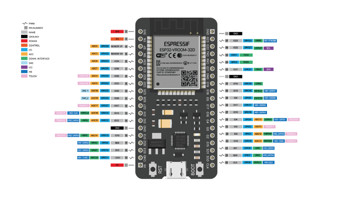
ESP-WROOM-32 Module
Methodology
First, the methodology outlines the complete process of assembling the web server, detailing both the back-end and front-end development. Following that, it presents the component testing procedures as well as the physical and electrical assembly of the prototype.
Web Server
The server instantiated on the ESP32 operates on a wireless network, which is a communications infrastructure that allows the transmission of data and information without the need for cables, using the IEEE 802.11 networking standard. This standard basically defines an architecture for WLANs that covers the physical and link levels. At the physical level, only radio frequency and infrared transmissions are handled. At the link level, IEEE has defined a medium access control protocol (MAC protocol), very similar to the protocol used in Ethernet local area networks (CSMA/CD). The IEEE 802.11 standard allows data transmission at speeds from 1 (mandatory) to 2 Mbps (optional) and specifies a common architecture, transmission methods, and other aspects of wireless data transfer, allowing interoperability between the various LAN products. The project's microcontroller has a wireless module that works with the IEEE 802.11 b/g/n standards, reaching maximum transmission rates of 11, 54, and 100 mb/s. With this module, it will be possible to create a web server instantiated on the microcontroller itself to control it through a Wi-Fi network with the aim of controlling the drone through an IP network and in future work building a network of autonomous drones.
The purpose of creating a web server is solely to control and monitor the drone. The server provides the client with a graphical interface that can be accessed via a browser on a Local Area Network (LAN). The web server architecture, as shown in the image below, consists of the server published on the ESP32 microcontroller, which communicates with the client on the network via a Wi-Fi network, and the server communicates with the sensor modules via I²C bus communication, in addition to performing dynamic control of the drone via PWM sent to the motor ESCs.
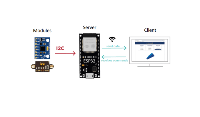
This project uses the Arduino IDE, which is responsible for compiling and loading the files into the microcontroller's flash memory. In order for communication between the IDE and the microcontroller to be established via a USB port, it is necessary to ensure that the driver for CP210X type chips is properly installed in the operating system. Chips of this type are responsible for the UART (Universal Asynchronous Receiver/Transmitter) serial communication integrated into the microcontroller. This driver is responsible for creating a virtual COM port that facilitates communication between the CP210X chip and the host computer.
FRONT-END: The server front-end concerns the client side and the visual interfaces, in which the “.html”, “.css” and “.js” files, respectively, were first coded, which together describe the behavior and the visual part of the server web page. This page is responsible for visually displaying the status of the drone and sending commands to the server. These commands were programmed in the “script.js” file and have direct interaction with the visual part described in the “index.html” file. The page was styled with the “style.css” file, which is an extension of the html file. These three files are sent to the microcontroller’s flash memory using the Serial Peripheral Interface Flash File System tool (SPIFFS), which was installed in the Arduino IDE software. This tool requires a unique architecture, as shown in the image below, to be able to load the files to the microcontroller.
BACK-END: The server backend is responsible for the configuration part, providing the application services and, specifically in this project, bridging the data coming from the client to the server, generating the PWM for the electronic speed controllers, processing the data read by the sensor modules and performing the dynamic control of the drone. The server code was written in the project's "ESP_WEB_SERVER_DRONE.ino" file, as shown in the image above. This file mainly configures the TCP/IP protocol and the initialization of the Wi-Fi communication on the LAN network, involving the configuration of the network port through the SSID and password parameters of the wireless network. It is also responsible for recognizing the front-end files, configuring the I²C bus communication with the sensor modules and programming the endpoints. In addition, it executes the PID control algorithm, sending PWM signals appropriately to the motor ESCs.
Component Testing
It is extremely important to test and ensure that all components are functioning properly before assembling them into a single functional module. Testing of the required components was done as described below.
GY-521 and VL53L1X Modules Testing: The web server implemented previously facilitated the testing of the gyroscope and accelerometer sensors present in the GY-521 module and the distance sensor present in the VL53L1X module. The data is captured by the sensors in analog format and converted to a digital format. The converted data is sent via the I²C bus to the server that was published on the ESP 32 microcontroller. The server web page that uses the “EventSource” interface to send events from the server to the client. These events contain data in standard json format already converted on the server itself to the international system and displayed directly on the client graphical interface. The gyroscope sensor was calibrated using a library offered by the manufacturer of the GY-521 module.
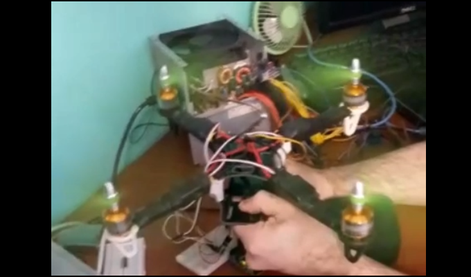
ESCs and Brushless Motor Testing: The ESCs recognize a PWM whose pulse width can vary between 1 ms and 2 ms. Outside this range, the ESCs do not recognize the signal and, therefore, will not function when they enter the recognition state. The motors will be at zero angular speed with 1 ms pulses and at maximum angular speed with 2 ms pulses. To properly test the motors, a library was used that is responsible for generating the PWM signal from the microcontroller to the ESC, which, in turn, generates the three motor power phases according to the PWM pulse width. In this way, the motors presented angular speeds proportional to the PWM. Initially, the ESCs were out of calibration in relation to the 1 ms to 2 ms pulse width window, resulting in different motor speeds for the same PWM signal. To calibrate them, it was necessary to connect all ESCs to the maximum pulse width of 2 ms for a few seconds and then immediately switch to the pulse width of 1 ms. This allowed the ATM32 microcontroller present in the ESCs to save the new operating pulse window of the motor phases. With all four ESCs going through the same process, they now share the same pulse width window. The image below shows the operation of the motors.
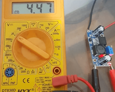
Step-Down Lm2596 Module Testing: To test the Lm2596 Step-Down converter, an external 12 V source was connected to the converter's power input. The positive and negative outputs were connected to the respective inputs of a multimeter configured to display the electrical potential difference. Then, the converter's trimpot responsible for regulating the output voltage was adjusted, in which a voltage lower than the input voltage can be observed using the multimeter, as shown in the image below.
3S LiPo Battery: To identify exactly which battery to use in the project, the entire system in which the motors were working at maximum speed together with the other components in parallel was connected to an external source and the current consumed by the system was measured, finding a peak of approximately 9A. The current obtained is the maximum current that the system needs to operate with the highest possible energy consumption. Therefore, a 20 C-Rating and 2.2Ah battery was chosen, which for the drone system is enough to power it without any significant risk.
Electric scheme
The figure below shows the complete electrical diagram of the drone in which the ESCs and the linear DC converter have been connected in parallel to the battery. The outputs of the DC/DC converter are connected to the power input of the ESP32 microcontroller. The 3 three-phase wires of the motors have been connected to the three-phase output wires of the ESCs respectively. The ESCs have PWM signal inputs which are connected to 4 pins of the ESP32 microcontroller. The connection of the 6 DOF gyro sensor and the laser sensor is done through the SCL and SDA ports of the ESP in parallel, so that the two sensors act as slaves and the microcontroller acts as the master in the I²C bus communication.
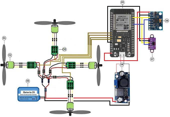
- Propeller.
- Brushless motor.
- Battery.
- Step-down converter.
- ESP32 microcontroller.
- MPU 6050 6 degree of freedom sensor.
- Vl53l1x distance sensor.
- ESC 30A.
For this work, a printed circuit board (PCB) was designed using the Proteus Design Suite software, which allowed the circuit described above to be arranged using an optimization tool to best rearrange the tracks on the board with a grounding mesh. The board was manufactured on the PCB-Proto 1S prototyping machine, which uses a copper-clad fiberboard along with the track and hole design file to manufacture the PCB, as seen in the following image.
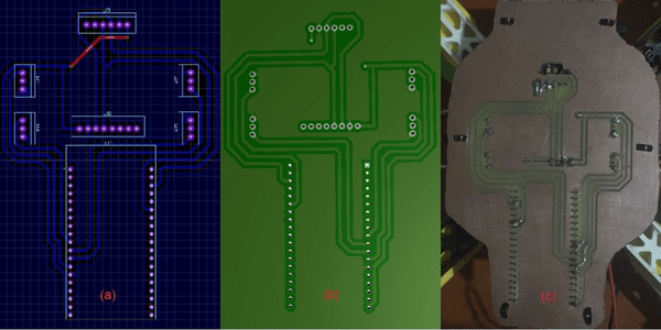
- Schematic design.
- 3D visualization.
- Fabricated PCB.
Assembly
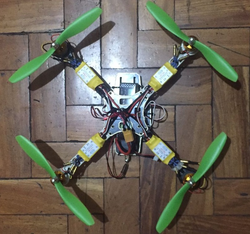
After individual component testing and PCB fabrication, the drone was assembled as follows: the A2212 brushless motors were properly mounted on the brackets located at the ends of the frame arms. The clockwise propellers were placed on the motor shafts on the black arms and the counterclockwise propellers were placed on the motor shafts on the white arms, respectively, as shown in the figure below. The four ESCs were fixed under the respective frame arms with nylon clamps. The PCB together with the soldered components was fixed to the bottom of the drone and the battery was fixed to the frame's cargo support structure.
Drone Dynamic Control System
This work aims to implement a control system in which the 4 engines work as system actuators, the MPU together with the distance sensor work as altitude and angular orientation sensors and finally the ESP32 microcontroller as the system controller. The image below shows the architecture of the system implemented in this work. Four reference values are received, which are the values of the roll, pitch and yaw angles and also the altitude in z, which are later passed to the altitude and attitude control that calculates the moments around x, y and z axis, and the vertical force, which are transformed into control commands for each engine. After receiving the engine rotation commands, the aircraft configuration variables are returned and passed to the altitude and attitude control blocks.

Altitude and Attitude Controller:It's responsible for controlling the altitude and the pitch, roll and yaw angles. Assuming that when controlling the altitude the angles do not vary, it can be said that the forces acting on the drone are given by:
Since the hovering condition corresponds to the equilibrium position, in which the forces generated by the engines correspond to the force generated by the attraction of gravity, equation (16) can be linearized with respect to the variation of the resulting force in z.
The attitude angles can be determined using Equation (14) using the following ordinary differential equations:
Simplifying the above ODEs to better design a controller for the system, we have:
For small movements around the balance point of the drone in individual transfer functions, apply a controller to the four variables independently, as can be seen in the image below.
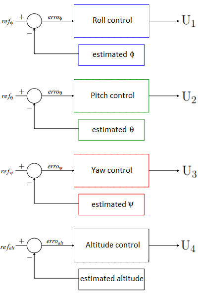
Four controllers can be implemented in parallel, operating in different ways, since the variables are decoupled under the considered operating conditions. The control of each angle and altitude is done by means of a proportional controller, in which the input error is the difference between the reference value and the desired value, and the output is the signal corresponding to the actuation force on the motors.
Calculation of Angular Velocity for Motors: The attitude and altitude control block outputs the control signals so that they can be mapped to calculate the angular velocity of the motors and generate the forces needed to actuate the drone. The equation can be written in matrix form as follows:
Simply invert to find the force on each drone motor:
The angular velocity can be found by the equation below:
Where km is a constant obtained from experimental tests of the motors used as actuators of the system. It is worth mentioning that the motors have physical limitations such as maximum power and torque that directly influence the maximum angular speed of the motor, and it is necessary to apply these restrictions to obtain a simulation close to reality. The system simulation is performed in the mathematical modeling software MATLAB using Equations (16), (18), (19) and (20) that determine the altitude, pitch, roll and yaw respectively through the propulsion forces generated.
Control Implementation: The altitude and attitude control block of the system was implemented with a P (proportional) controller to be applied to the 4 controllers that receives the reference value to calculate the error according to the desired value and applies it to the signal.
    Algorithm 1: Digital Proportional Control
    Input: gain P; reference value ref; estimated value des, time dt;
    output: U;
    BEGIN
       REPEAT
            error ← (ref − des)
            U ← P ∗ (error)
        UNTIL at end of simulation time;
    END
Results
To simulate the controller responses regarding attitude and height angles, the tools available in the MATLAB mathematical modeling software were used. The simulations represent the step response of the transfer functions obtained through Equations (17), (21), (22) and (23). The values chosen for the parameters used in the test are based on and approximated by the drone developed in the project (Inertial structure of the drone Image):
Therefore, the inertia parameters are:
The following images show the step response of 0.26 (the value of 0.26 in practical terms corresponds to 15◦) in the attitude system of the pitch, roll and yaw angles and also the step response of 100mm in the altitude system, all in closed loop. Tests were assigned to both the proportional controller and the proportional derivative controller with the value of KP = 1 and KD = 1.
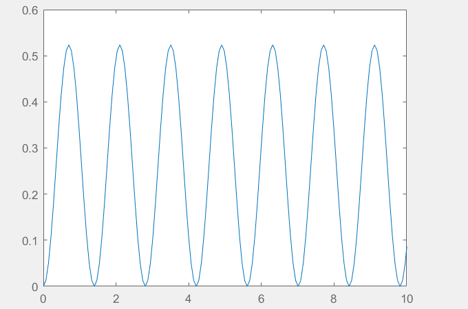
0.26 rad step response KP = 1 closed-loop for pitch and roll - Rads/sec Chart
For better response time of the altitude system, the PID Tuner tool from the MATLAB Control System Toolbox was used to better find the values of Kp, Kd and Ki that stabilize in steady state quickly with low overshooting, as shown in the image below.
To test the attitude controllers, only one of the axes was manually rotated so that the other two remained fixed, and the process was repeated for all other two fixed axes. To test the altitude control, all three axes were manually fixed and the drone was moved vertically towards the ground. The graphs illustrated in the following images were obtained from the web server page using the “chartjs” framework. A graph was implemented to display the signal values of the 4 motors according to the height and attitude angles as a function of time. The motor signal values are PWM signals ranging from 0 to 100. The angles are in degrees, the height is presented in millimeters and finally the time is given in seconds.
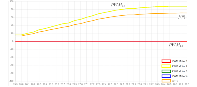
Pitch control PWM responses
Conclusion
The complete assembly of a drone and the integration of all components up to the final prototype phase require a lot of theoretical and practical knowledge. The project contains several stages, the main ones being: physical, mechanical and electronic assembly, system modeling, simulations and tests. In this work, altitude and attitude control via Wi-Fi was implemented through a client-server service with the objective of giving the aircraft aerial stability. Although PID control is relatively easy to implement, reconciling it with practice is a task that involves several mechanical and electromagnetic complications that implicitly affect the project.
After the design and implementation of the drone in its entire system, it was concluded that there are still some improvements to be made, such as implementing techniques to improve the stability of the control system, improving the server's response to the client, optimizing the microcontroller's resources, among others. The following future work is proposed: design and implement position control to give the drone autonomy in spatial movement. Implement disturbance treatment in the system to correct alleged errors in reading the model output variables, variation in the system mass, among others. Implement gain scaling technique to compensate parameter variables and linearity approximations of the plant model.